Chopper Amplifier Tutorial
â The values of L and C are chosen depending upon the requirement of output voltage and current. Step Up chopper boost converter Step Down ChopperBuck converter Step UpDown Chopper Buck-boost converter Step Up Chopper.
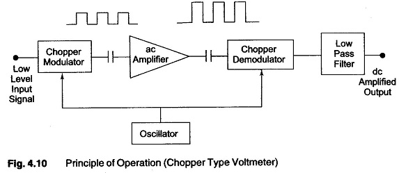
Chopper Type Dc Amplifier Voltmeter Principle Of Operation Advantages Eeeguide Com
The best bipolar amplifiers offer offset voltages of 25 µV and 01 µVºC drift.

Chopper amplifier tutorial. Modern chopper-stabilized op amps. Pss pss fund100k harms3 errpresetconservative. What is a chopper.
â Step-up chopper is used to obtain a load voltage higher than the input voltage V. Comparators ADCs and DACs require amplifiers with microvolt offsets Also many sensors eg. Depending on the voltage output choppers are classified as.
The average voltage output V o in a step up chopper is greater than the voltage input V s. Smart Sensor Systems 02 Kofi AA. The end result is a much lower limit on signals.
The chopper amplifier was then simulated at the behavioral level using MATLAB. From Analog Devices MT-055 tutorial. The classic chopper amplifier.
This reverse power flow from the load to the source will occur only if the load is active. A Lock-in Amplifier and Mechanical Chopper. A chopper stabilized amplifier is an electronic circuit that employs a modulation technique to reduce or eliminate dc offset and low-frequency noise in op amps.
Circuit Techniques for Reducing the Effects of Op-Amp Imperfections. Note that it is not the secondary itself. For the lowest offset and drift performance chopper-stabilized auto-zero amplifiers may be the only solution.
Autozeroing Correlated Double - Proceedings of the IEEE Author. AuthorsQinwen Fan Kofi MakinwaAbstractCCIAs have been extensively explored over the past decade. Major improvements include techniques to boost input-impe.
Chopper amplifier Since we need to put 2 pulse signal as 2 phases If we use transient sim how to simulate the AC gain of the amplifier. Trying to simulate a chopper amplifier. â When the chopper is ON the inductor L is connected across the supply.
If we use a conventional amplifier with low-pass response the noise and signal cannot be separated by filtering in the following stages. The Class-B chopper or Type-B Chopper is also called as Step Up chopper because the power can be transferred from a lower voltage V 0 to higher voltage V S only. Chopper Stabilized Auto-Zero Precision Op Amps.
In this frequency range there is huge 1f noise added by amplifier. Low Level Optical Detection using Lock-in Amplifier Techniques 4 discrete frequencies or noise voltages not equal to the reference frequency will be rejected by the lock-in amplifier. The Keck IFSM for Infrared Fast Steering Mirror has both an f40 secondary mirror.
Menolfi QHuang A 200nV 65 nVHz noise PSD 56kHz chopper instrumentation amplifier Digest of ISSCC 2001 p. A chopper is a mechanism which allows a secondary mirror to be rapidly tilted back and forth. Thus a single chopping mechanism could be used with different secondary mirrors.
There is only one clock all the non overlapping clocks ect are derived from it. In CMOS amplifiers component mismatch can easily give rise to offsets of several millivolts. Thermopiles bridges hall-effect sensors etc output DC signals that need to be processed with microvolt precision This tutorial will focus on dynamic offset-cancellation DOC techniques with which offset can be reduced to the microvolt level.
ŁAlso called Auto-Zero Auto-Null Ping-Pong Stabilized and Commutated Amplifier. The problem is that the flicker noise is not being reduced on the input noise plot when I use the following pnoise pss settings. The chopper amplifier relied on the simple premise that using 1950s technology it was difficult to make a good DC amplifier.
ŁA chopper amplifier is often a compound amplifier. The figure below shows a configuration of a step up chopper. A chopper amplifier is designed to amplify very low frequency signal such as EEG and ECG.
However this can be reduced to the microvolt level by the appl. Chopper Amplifiers ŁA chopper amplifier is a type of amplifier that exhibits precise outputs and low noise. For testing it is configured as a voltage follower.
Figure below shows the Circuit Diagram and Waveform of step up chopper. Finally a full Veriloga-A model of the chopper amplifier along with the ECoG electrodes was developed and the circuit was simulated at the electrical level using Cadences Spectre simulator.

Chopper Amplifier Diagram Ece Amplifier Block Diagram Electronics Projects
Edacafe Com Videos Tutorials Chopper Stabilized Amplifier

Chopper Op Amps And Noise Edn

Chopper Amplifiers Demystified Kofi A A Makinwa Youtube


Comments
Post a Comment